

Methods of Coating Thickness Measurement
-
- June 2, 2021
Coating film thickness is a crucial variable that plays a role in product quality, process control, and cost control. measurement of film thickness can be done with many different instruments. Understanding the available equipment for film thickness measurement and how to use it is useful for every coating operation.
The culmination that determines what method is best for a given coating measurement includes the type of coating, the substrate material, the thickness range of the coating, the size and shape of the part, and the cost of the equipment. Commonly accepted measuring techniques for cured organic films incorporate nondestructive dry film methods such as magnetic, eddy current, ultrasonic, or micrometer measurement and also destructive dry film methods such as testing using a microscopic method such as ASTM B487-20 or gravimetric (mass) measurement.
Methods are also available for powder and liquid coatings to measure the film before it is cured.

Magnetic Film Thickness Gauges
Magnetic film gauges are used to nondestructively measure the thickness of a nonmagnetic coating on ferrous substrates. Most coatings on steel and iron are measured this way. Magnetic gauges use one of two principles of operation: magnetic pull-off or magnetic/electromagnetic induction.
Magnetic Pull-off Thickness Gauges
Magnetic pull-off gauges use a permanent magnet, a calibrated spring, and a graduated scale. The attraction between the magnet and magnetic steel pulls the two together. As the coating thickness separating the two increases, it becomes easier to pull the magnet away. Coating thickness is determined by measuring this pull-off force. Thinner coatings will have a stronger magnetic attraction, while thicker films will have a comparatively less magnetic attraction. Testing with magnetic gauges is sensitive to surface roughness, curvature, substrate thickness, and the composition of the test material.
Magnetic pull-off gauges are rugged, simple, inexpensive, portable, and usually do not require any calibration adjustment. They are a good, low-cost alternative in situations where quality goals require only a few readings during production.
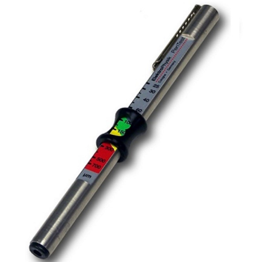
Pull-off gauges are typically pencil-type or rollback dial models. Pencil-type gauge models (Figure 1) use a magnet mounted to a helical spring that works perpendicularly to the coated surface. Most pencil-type pull-off gauges have large magnets and are designed to work in only one or two positions, partially compensating for gravity. More accurate versions are available with tiny, precise magnets to measure on small, hard-to-reach surfaces. A triple indicator ensures accurate measurements when the gauge is pointed down, up, or horizontally with a tolerance of ±10%.

Figure 1. Pencil-type magnetic pull-off thickness gauge.
Rollback dial models (Figure 2) are the most common form of magnetic pull-off gauge. A magnet is attached to one end of a balanced pivoting arm and connected to a calibrated hairspring. By rotating the dial with a finger, the spring increases the force on the magnet and pulls it from the surface. These gauges are easy to use and have a balanced arm that allows them to work in any position, independent of gravity. They are safe in explosive environments and are commonly used by painting contractors and small powder coating operations. Typical tolerance is ±5%.
Figure 2. Rollback dial magnetic pull-off thickness gauge.
Magnetic and Electromagnetic Induction Instruments
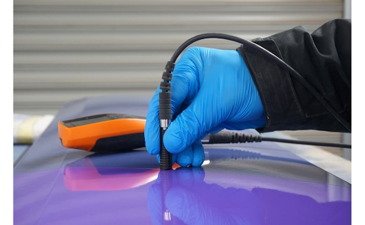
Magnetic induction instruments (Figure 3) use a permanent magnet as the source of the magnetic field. A Hall-effect generator or magneto-resistor is used to sense the magnetic flux density at a pole of the magnet. Electromagnetic induction instruments use an alternating magnetic field. A soft, ferromagnetic rod wound with a coil of fine wire is used to produce a magnetic field. A second coil of wire is used to detect changes in magnetic flux.
These electronic instruments measure the change in magnetic flux density at the surface of a magnetic probe as it nears a steel surface. The magnitude of the flux density at the probe surface is directly related to the distance from the steel substrate. By measuring flux density, the coating thickness can be determined.
Figure 3. Electronic, magnetic induction thickness gauges.
Electronic, magnetic gauges come in many shapes and sizes. They commonly use a constant pressure probe to provide consistent readings that different operators do not influence. Readings are shown on a liquid crystal display (LCD). They can have options to store measurement results, perform instant analysis of readings, and output results to a printer or computer for further examination. Typical tolerance is ±1%.
The manufacturer’s instructions should be carefully followed for the most accurate results. Standard test methods are available in ASTM D7091, ISO 2178, and ISO 2808.

Eddy Current Thickness Gauges
Eddy current techniques are used to nondestructively measure the thickness of nonconductive coatings on nonferrous metal substrates. A coil of fine wire conducting a high-frequency alternating current (above 1 MHz) is used to set up an alternating magnetic field at the surface of the instrument’s probe. When the probe is brought near a conductive surface, the alternating magnetic field will set up eddy currents on the surface. The substrate characteristics and the distance of the probe from the substrate (the coating thickness) affect the magnitude of the eddy currents. The eddy currents create their opposing electromagnetic field sensed by the exciting coil or by a second, adjacent coil.
Eddy current coating thickness gauges look and operate like electronic, magnetic gauges. They are used to measure coating thickness over all nonferrous metals. Like magnetic, electronic gauges, they commonly use a constant pressure probe and display results on an LCD. They can also have options to store measurement results or perform instant analysis of readings and output to a printer or computer for further examination. The typical tolerance is ±1%. Testing is sensitive to surface roughness, curvature, substrate thickness, type of metal substrate, and distance from an edge.
Standard methods for the application and performance of this test are available in ASTM B244 and ISO 2360.
It is now common for gauges to incorporate both magnetic and eddy current principles into one unit. Some simplify the task of measuring most coatings over any metal by switching automatically from one principle of operation to the other, depending upon the substrate. These combination units are popular with painters and powder coaters.
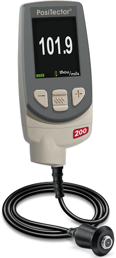
Ultrasonic Thickness Gauges
The ultrasonic pulse-echo technique of ultrasonic thickness gauges is used to measure the thickness of coatings on nonmetal substrates (plastic, wood, etc.) without damaging the coating.
Figure 4. The ultrasonic gauge can measure the thickness of coatings on nonmetallic substrates.
The probe of the instrument contains an ultrasonic transducer that sends a pulse through the coating. The pulse reflects from the substrate to the transducer and is converted into a high-frequency electrical signal. The echo waveform is digitized and analyzed to determine coating thickness. In some circumstances, individual layers in a multi-layer system can be measured.
The typical tolerance for this device is ±3%. Standard methods for the application and performance of this test are available in ASTM D6132.
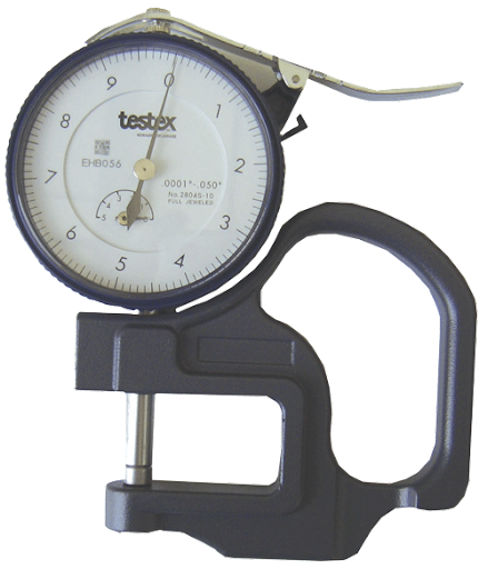
Micrometer Thickness Gauges
Micrometers are sometimes used to check coating thickness. They have the advantage of measuring any coating/substrate combination but the disadvantage of requiring access to the bare substrate. The requirement to touch both the coating surface and the underside of the substrate can be limiting, and they are often not sensitive enough to measure thin coatings.
Two measurements must be taken: one with the coating in place and the other without. The difference between the two readings, the height variation, is taken to be the coating thickness. On rough surfaces, micrometers measure coating thickness above the highest peak.
Destructive Tests
One destructive thickness technique is to cut the coated part in a cross-section and measure the film thickness by viewing the cut microscopically using a light optical microscope. Another cross-sectioning technique uses a scaled microscope to view a geometric incision through the dry-film coating. Precision cutting wheels are used to make a small, precise V-groove through the coating and substrate. Gauges are available that come complete with cutting tips and an illuminated scaled magnifier.
While the principles of this destructive method are easy to understand, there are opportunities for measuring error. It takes skill to prepare the sample and interpret the results. Adjusting the measurement reticule to a jagged or indistinct interface may create inaccuracy, particularly between different operators. This method is used when inexpensive, nondestructive methods are not possible or as a way of confirming nondestructive results. ASTM D4138 outlines a standard method for this measurement system.
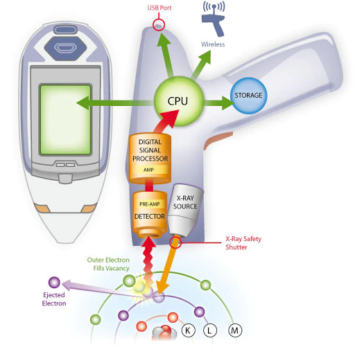
X-Ray Fluorescence Method
X-ray fluorescence is a nondestructive and contactless method to determine the layer thickness and perform a material analysis of metallic coated materials to DIN to DIN EN ISO 3497. This method can determine the layer thicknesses and the compositions of unique layers, multiple layers, and alloyed layers.
Gravimetric Thickness Gauges
By measuring the mass and area of the coating, the thickness can be defined. The simplest method is to weigh the part before and after coating. Once the mass and area have been determined, the thickness is calculated using the following equation:
T = (m x 10) / (A x d)
T is the thickness in micrometers, m is the mass of the coating in milligrams, A is the area tested in square centimeters, and d is the density in grams per cubic centimeter.
It is difficult to relate the mass of the coating to thickness when the substrate is rough or the coating uneven. Laboratories are best equipped to handle this time-consuming and often destructive method.

Thickness Measurement before Cure
Wet-film thickness (WFT) gauges help determine how much material to apply wet to achieve a specified dry-film thickness presented that the percent of solids by volume is known. They measure all wet organic coatings, such as paint, varnish, and lacquer on flat or curved smooth surfaces.
Measuring wet film thickness during the application identifies the need for prompt correction and adjustment by the applicator. After it has dried or chemically cured, correction of the film requires costly extra labor time, may lead to contamination of the film, and may introduce coating adhesion and integrity of the coating system.
The equations for determining the correct wet-film thickness (WFT), both with and without thinner, are as follows:
Without thinner:
WFT = (desired dry film thickness) / (% of solids by volume)
With thinner:
WFT = (desired dry film thickness / % of solids by volume) / (100% + % of thinner added)
Wet-film is most often measured with a wet film comb or wheel. The wet-film comb is a flat aluminum, plastic, or stainless steel plate with calibrated notches on the edge of each face. The gauge is placed squarely and firmly onto the surface to be measured directly after coating application and then lifted. The wet film thickness lies between the highest coated notch and the next uncoated notch. Notched gauge measurements are neither accurate nor sensitive. Still, they are useful in determining the approximate wet-film thickness of coatings on articles where size and shape prohibit more precise methods.
The gauge should be used on flat surfaces, free from imperfections, and should be used along the length, not the width, of curved surfaces. Using a wet-film gauge on quick-drying coatings will yield inaccurate measurements. ASTM D4414 outlines a standard method for the measurement of wet-film thickness by notch gauges.
A wet film wheel (eccentric roller) uses three disks. The gauge is rolled in the wet film until the center disk touches the wet film. The point where it makes contact provides the wet film thickness. Powder coatings can be measured before curing with a simple hand-held comb or an ultrasonic gauge. The uncured powder film comb works much the same way as a wet film gauge. The comb is dragged through the powder film, and the thickness lies between the highest numbered tooth that made a mark and has powder clinging to it and the next highest tooth that left no mark and has no powder clinging to it. These gauges are comparatively cheap, with an accuracy of ±5 mm. They are only suitable as a guide since the cured film may be different after flow. Marks left by the gauge may alter the characteristics of the cured film.
An ultrasonic device can be used nondestructively on uncured powder on smooth metallic surfaces to predict the thickness of the cured film. The probe is positioned a short distance from the surface to be measured, and a reading is displayed on the LCD of the device.
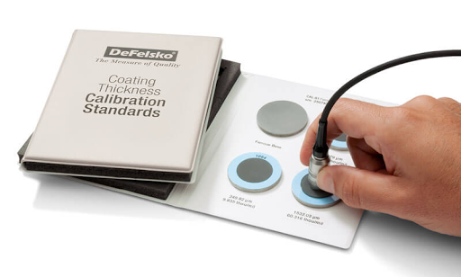
Coating Thickness Standards
Coating thickness gauges are calibrated to known thickness standards. There are many thickness standards, but it is best to ensure they are traceable to a national measurement institute such as NIST. It is also important to verify that the standards are at least four times as accurate as of the gauge they calibrate. A regular check against these standards verifies the gauge is operating properly. When readings do not meet the accuracy specification of the gauge, the gauge must be adjusted or repaired and then calibrated again.
Summary
Film thickness in coatings can have a big impact on price and quality. Determination of film thickness should be a recurring event for all protective coating applicators. The correct gauge to use depends on the thickness range of the coating, the shape and type of substrate, the cost of the gauge, and how critical it is to get an accurate measurement.